Fixing Anime Face Perspective in Unity
A practical experiment in reducing perspective drift on a stylized anime face with a small camera-relative vertex correction.

On this page⌄
The problem in motion
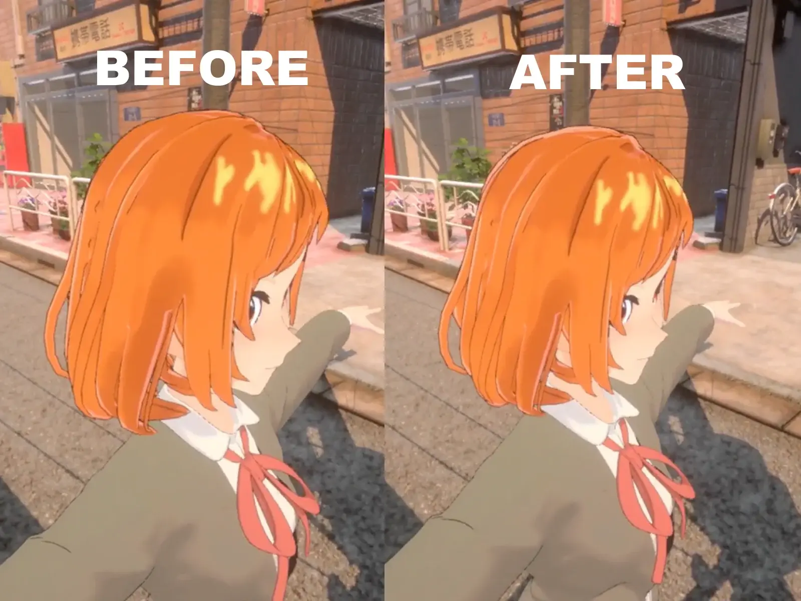
From the front, the face reads correctly. Move the camera closer or rotate into a three-quarter view and the near side starts to carry more visual weight than the far side.
That drift is especially noticeable on anime-style faces. Large eyes, shallow noses, and carefully controlled cheek and jaw silhouettes are often designed around a particular projected image, not around perfectly physical depth from every angle.
Perspective projection is doing exactly what it should: parts of the mesh that are closer to the camera appear larger. The problem is that this can undo proportions that were intentional in the reference pose.
I ran into this while testing a character shader and wanted to compensate for the drift without changing the camera, replacing the mesh, or authoring a corrective pose for every angle.
Why this happens
Perspective projection makes objects appear smaller as their distance from the camera increases. On a realistic head that usually reads naturally; on a stylized face, the same depth difference can make one eye, cheek, or side of the jaw dominate the silhouette.
The model may be intentionally flat in some areas and exaggerated in others. That means the camera can expose a proportion change that was never meant to be judged from that angle.
The nose may barely protrude from the face. The eyes may be unusually large and placed on a relatively flat surface. The jaw and cheeks can be shaped specifically to preserve a certain silhouette from a few important angles.
Moving the camera farther away and changing the field of view can hide some of the effect, but that changes the shot for everything else in the scene.
I wanted the camera to remain a cinematography decision rather than something dictated by one character's face.
Letting the mesh cheat
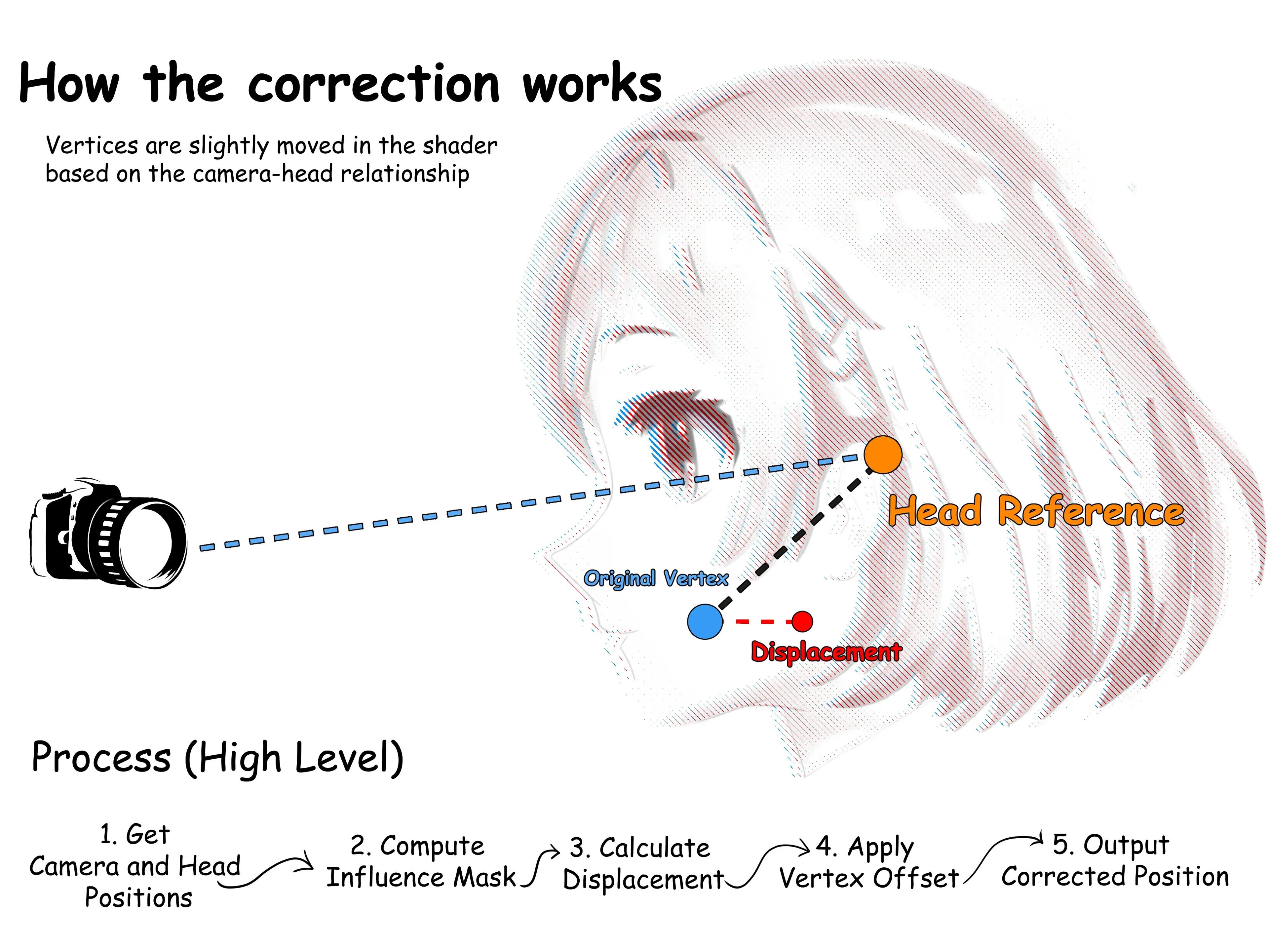
The shader compares each vertex with the camera and a stable point on the head, then moves only the part of the mesh that should keep its projected shape.
The flow is: camera direction → head-relative position → spatial masks → depth correction → final vertex position.
Camera → head-relative direction → spatial mask → correction → vertex positionThe mesh asset itself never changes.
Because the deformation happens in the vertex shader, it can respond continuously as the camera moves instead of being limited to a few predefined poses or a per-frame mesh update from C#.
Choosing a reference point
The camera position alone is not a useful reference for the correction. The shader also needs a stable point on the character so the same calculation follows the head when the character moves through the scene.
For a humanoid character, I use the head bone as that reference. From there the shader can compare the camera position, head position, and vertex position in the same character-relative setup.
From there we have:
- camera position,
- head position,
- vertex position,
- and the direction the camera is viewing the head from.
Keeping the calculation relative to the character means moving the character does not change how the correction behaves.
Correct only the part that needs it
Applying perspective compensation to the entire mesh would distort the neck, torso, and accessories along with the face. The effect therefore needs a spatial mask.
I use two controls: a radial mask that fades with distance from the head reference point, and a height mask that limits where the correction fades in and out.
final influence = radial mask × height mask × correction strengthThat gives enough control to keep the useful deformation around the face while leaving most of the neck, torso and surrounding geometry alone.
The vertex correction
Once the masks decide how strongly a vertex participates, the actual operation stays small. The implementation calculates a camera-relative direction, flattens the selected part of the vertex position toward that direction, and blends between the original and corrected positions.
- calculate the camera-relative direction;
- determine how far the vertex is from the correction region;
- calculate the mask;
- move the vertex by a small amount;
- blend between the original and corrected positions.
In simplified form:
float influence = radialMask * heightMask * correctionAmount;

float3 correctedPosition = CalculatePerspectiveCorrection(
    positionOS,
    cameraPositionWS,
    headPositionWS
);

positionOS = lerp(
    positionOS,
    correctedPosition,
    influence
);There is no single magic formula here. The useful properties are that the correction is continuous, camera-driven, and spatially controlled.
Getting the camera data into the shader
The shader still needs a few values that vary per character:
- head position,
- camera position,
- correction settings,
- and optionally a custom perspective camera.
A small runtime component provides the values that change per character: the head position, camera position, correction amount, radius, height range, and an optional custom camera.
renderer.GetPropertyBlock(propertyBlock);

propertyBlock.SetVector(
    "_HeadBonePositionWS",
    headTransform.position
);

propertyBlock.SetVector(
    "_MainCameraPositionWS",
    targetCamera.transform.position
);

renderer.SetPropertyBlock(propertyBlock);I pass those values with a MaterialPropertyBlock, so characters can keep sharing the same material instead of creating a separate material instance for every renderer. The component supplies data; the shader owns the deformation.
A real implementation
I first tested the approach by integrating it into my own lilToon fork, where I could judge it against real character materials, animation, and lighting instead of an isolated shader preview.
The technique is not tied to lilToon, but the fork makes the split between runtime data and the shared vertex path concrete.
The useful part of the fork is not that everyone should use the same shader. It is a reference for keeping the runtime component small while the actual correction stays in the vertex stage.
foreach (Renderer targetRenderer in targetRenderers) { if (targetRenderer == null) continue; targetRenderer.GetPropertyBlock(propertyBlock); propertyBlock.SetVector(HeadPositionId, headPosV4); propertyBlock.SetVector(CameraPositionId, camPosV4); propertyBlock.SetFloat(UseCustomCameraId, customCamFloat); propertyBlock.SetFloat(AmountId, clampedAmount); propertyBlock.SetFloat(RadiusId, clampedRadius); propertyBlock.SetFloat(StartHeightId, startHeight); propertyBlock.SetFloat(EndHeightId, endHeight); targetRenderer.SetPropertyBlock(propertyBlock); } float3 worldPosOriginal = vertexInput.positionWS; float3 worldPos = lilToAbsolutePositionWS(worldPosOriginal); float3 headPosWS = _HeadBonePositionWS.xyz; float3 renderCameraPositionWS = lilGetPerspectiveCameraPositionWS(); float3 camPosWS = lerp( renderCameraPositionWS, _MainCameraPositionWS.xyz, saturate(_UseCustomPerspectiveCamera) ); float3 charUp = normalize((float3)UNITY_MATRIX_M._m01_m11_m21); float vertH = dot(worldPos, charUp); float headH = dot(headPosWS, charUp); float h0 = headH - _PerspectiveRemovalStartHeight; float h1 = headH + _PerspectiveRemovalEndHeight; float headRegion = smoothstep( h0, max(h1, h0 + 1e-4), vertH ); float3 fromHead = worldPos - headPosWS; float distanceFromHead = length(fromHead); float radialMask = saturate( 1.0 - distanceFromHead / max(_PerspectiveRemovalRadius, 1e-4) ); radialMask = smoothstep(0.0, 1.0, radialMask); float strength = saturate(_PerspectiveRemovalAmount) * saturate(_Perspective) * headRegion * radialMask; float3 cameraOffset = camPosWS - headPosWS; float cameraDistance = max(length(cameraOffset), 1e-4); float3 cameraDirection = cameraOffset / cameraDistance; float depthOffset = dot(fromHead, cameraDirection); float3 flattenedPos = worldPos - cameraDirection * depthOffset; float3 finalWorldPos = lerp(worldPos, flattenedPos, strength); float3 displacement = finalWorldPos - worldPos; worldPos = worldPosOriginal + displacement; vertexInput.positionWS = worldPos; vertexInput.positionCS = mul( UNITY_MATRIX_VP, float4(worldPos, 1.0) ); float3 viewDirection = normalize(lilViewDirection(lilToAbsolutePositionWS(vertexInput.positionWS))); float3 headDirection = normalize(lilHeadDirection(lilToAbsolutePositionWS(vertexInput.positionWS)));Correction in action
This effect is easier to judge in motion than from code alone. Compare the right side for the final render and the left side for the vertices being adjusted while the camera moves.
The clip is intentionally a side-by-side comparison: the final output should keep the facial proportions readable, while the deformation view shows that only a bounded region is being changed.
Where it breaks down
This is not a replacement for modelling. If the face does not work in profile, it still needs a better profile. The shader can only compensate for a bounded projection problem.
Stronger correction can also create problems around eyelashes, hair close to the face, accessories, the ears, or the transition between the face and neck.
The more aggressively the vertices move, the easier it becomes to notice that something unnatural is happening.
A shader can apply a rule, but it can't understand artistic intent. It can't decide that one eye should sit slightly higher from a specific angle simply because that version reads better.
That's where authored corrections start to make more sense.
Final thoughts
Stylized rendering is already full of deliberate cheats.
Shadows are shifted because they look better elsewhere. Normals are edited to control lighting. Highlights ignore physics. Facial features change shape from one drawing to the next.
So I don't think a 3D character always needs to preserve perfectly physical projection either. Sometimes the model is already right for the image you're trying to make. It just needs a little help once the camera starts moving.
That's what I like about this technique. It doesn't remove perspective - it gives you one more controlled way to decide how much of it the character should keep.